Control Console
After many variations of controlling Tesla coils, this is probably the final version.I started my HV projects with just a 11KV 18mA OBIT, then got a 10KV 50mA NST, then got another, so each time meant an upgrade to how I control them, add to that a rotary gap, and the possibility of controlling other things (mains and low voltage), I decided to incorporate many more features that I currently need.
I got a 8 Amp variac, then got a 5 Amp variac.
the build was on.
The control unit has the 2 variac's (8A and 5A), 2 switched mains outputs (240 volts), 4 switched 12 volt DC outputs, all of these are available from the back panel, or via an umbilical to a connection block mimicking the back panel, the umbilical is a 12 pin cinch connector, care had to be taken as there are 2 different voltages.
I did have a 240V to 55V isolation transformer in the primary of the smaller variac that could be switched in and out, this was so the small variac could provide isolated 0-55V output, but I decided to remove that due to extra weight and the amount of times i might use it, much better to connect that externally if needed.
A built in power supply with +/-12, 5, and 3.
3 volts and a separate USB socket with regulator completes the supplies.
Metering consists of a main volt/current meter on the input to the unit, a volt meter and ammeter for each of the variac supplies.
I started off with a couple of voltmeters I happened to have, but they proved useless, the front was plastic, if you rub your hand across the face, the needles would move and stick due to static, so a pair of new meters replaced them.
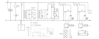
The circuit is below

You will also notice a start/stop arrangement that has a keyswitch, when power is applied to the console, the meters light up and the low voltage supplies are powered, the multipin socket connects to a led 3 section sign, the 'High Voltage' section illuminates, when a key is inserted and turned, the 'enabled' section also illuminates, when the start button is pressed, a double pole relay allows power to the variac's and the switched mains outputs, the enabled light goes out to be replaced by the 'active' light.
Also with the start/stop circuit is a remote control, the only connectors i had to hand were XLR, but this suits me fine, i can either use a bypas plug or the remote cable and buttons.
Power Off |
Power on |
Keyswitch operated |
start button pressed |
Since taking the photo's below, I have added a dimmer control which is situated to the right of the voltmeters, the dimmer goes out to a double socket on the back and is useful for running the coil in the back garden to control a couple of 150W floodlights.
Overview of console |
Metering, the input meter is on the right |
The 2 Variac's. enabling and bypass switched |
2 12v auxiliaries &l3 l4 power switches |
Local power - 24v AC and power supply |
Inside the base |
Inside the front panel |
Rear of the console, note the umbilical socket resting on top and the cinch plug |
You may freely link to any content or page. You may not hotlink any images etc You may copy any snippet of information providing you credit me with the creation