Multi Bobbin
I got to thinking when i saw people using several transformers with the primaries in parallel, and the secondaries in series to produce high voltages.I had a collection of old transformer plugs from some old equipment, (my transformers were about 500mA output), so i broke them all open and found 4 that were the same size, if you're lucky you'll find that the primary and secondary are on separate bobbins, here's the process
With the help of a 'stanley' knife to release the laminations and a pair of pipe grips to pull the laminations out i was then able to remove the bobbins from the holder (you can throw out the holders) making 4 primaries and 4 secondaries.
The laminations are usually 'E' and 'I' shaped. Make sure that the bobbins don't have any protrusions, carefully use a file if you have to, but the bobbins need to sit close together
Also worth checking, some transformers have a heat fuse that will go open circuit if the winding gets hot, if you are using second hand transformers and they are open circuit, the heat fuse is probably blown, you may be able to find this under the tape of the winding and remove.
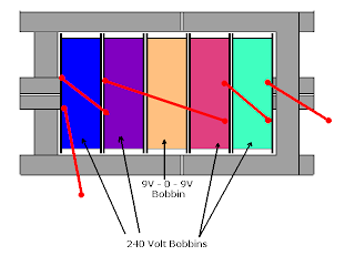
Now for the hard part, looking at the diagrams below you need to assemble 4 secondaries and a primary on the laminations, start with one secondary, insert the laminations taking careful note to alternate them, you'll find that 2 'I' laminations will (usually) fit side by side in the core, at this point you don't need to worry about the sides,
Once the first bobbin is full of laminations, add another secondary, you can also add more core laminations followed by the primary and other secondaries. Complete by adding the E and I cores to the other end, followed by the I cores on the sides
As can be seen in the diagram, I like to position the wires outwards from the primary, with the primary wires on the other side.
The ends of the core were a bit longer than the bobbins so they stick out, this isn't a problem, you should also varnish the laminations so they don't 'rattle'
Hopefully you already checked the windings before assembly, you now need to work out the polarity. Use an analogue meter movement if possible, you may need a resistor in series to reduce the voltage going to it, i found it a good idea to also add a diode in series so the resultant pulse will move it. Connect to one secondary, now put a small voltage on the primary, then remove, note when the meter deflects, the wire with the diode connected we'll call 'Start', do this with all 4 secondaries noting when you get deflection, and which you identify as Start.
After identifying polarity, connect the 'finish' of coil 1 to the start of coil 2 etc, all secondary coils should be wired in series.

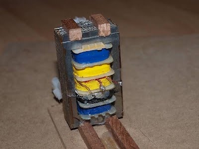
The Bobbins in place on the laminations, don't worry about the ends of the laminations sticking out, as i found, this can be useful for mounting. The primary connections are on the other side.

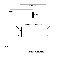
I've done some basic tests with just the power transistors connected to the primary Be warned, most normal voltmeters will not have the range to test the voltage as it's likely to be well over 1000 volts.

The transistors will be connected to an astable multivibrator, though you could connect to a 555 based circuit with enough drive power. Hopefully the voltage will be well in excess of 1000V AC, and if bridge rectifiers are added with a capacitor, this could be even higher.
This may seem a lot of work, but this makes 4 transfromers smaller, and only one primary to power.
I found the best plug power supplies are the DC ones as they are more likely to have centre tapped secondaries. If you're unlucky enough to only have single winding secondaries, then placing 2 together and joining in series will have the same effect, though the transformer will then be a bit longer.
Here's the result of all that work:
This is how I started adding the laminations just with one bobbin

The low voltage primary side showing the centre tapped connections

The secondary side with the connections in series

The inverter circuit added, currently it's just an astable multivibrator with a couple of power transistors connectced to the collectors of the astable, but i need to add a couple of darlington PNP transistors

On test i'm getting about 650 Volts AC, the darlingtons should change that.
You may freely link to any content or page. You may not hotlink any images etc You may copy any snippet of information providing you credit me with the creation